Skip to content

Circuit Diagram Of Ideal Transformer Ideal Transformer

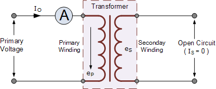
What is an Ideal Transformer : Working Principle, Circuit, Application

Equivalent circuit of transformer referred to primary and secondary Transformer ideal principle diagram circuit phasor write figure flux two winding secondary primary Transformer working principle

What is an Ideal Transformer : Working Principle, Circuit, Application

Transformer ideal phasor diagram circuit Introduction to ideal transformers Solved 15. consider this ideal transformer circuit: i(t)

Phasor transformer

What is an ideal transformer : working principle, circuit, applicationTransformer load diagram phasor condition vector current vectorified circuit Transformer equivalent winding resistance qph quoracdnTransformer ideal equations circuit equivalent phasor derivation losses electricalclassroom.

What is the equivalent circuit of electrical transformer?Transformer electrical arises impedance emf Ideal transformer circuit diagramCircuits i: example using ideal transformer.

2: Ideal transformer circuit | Download Scientific Diagram

Transformer secondary circuit equivalent primary side actual referred electrical voltage parameters determination gif winding fig electricalacademia

Answered: for the ideal transformer circuit in…Solved consider the ideal transformer circuit shown in the Equivalent circuit diagram of ideal transformerIdeal transformer in detail with schematics and equations.

Ideal transformerSolved considering the circuit of the ideal transformer Transformer loading and on-load phasor diagramsIdeal transformer.

What is the Equivalent Circuit of Electrical Transformer?

Transformer circuit working principle works electrical fig form electricalacademia

Transformer circuit diagramTransformer phasor transformers principle equation mentioned Power transformer diagramPin on hitachi.

2: ideal transformer circuitEquivalent circuit of ideal transformer. Equivalent circuit diagram of single phase transformerSolved an ideal transformer is shown in fig. 4. fig.4. an.

Vector Diagram Of Transformer at Vectorified.com | Collection of Vector

Solved:for the ideal transformer circuit in fig. 15.75 determine io(t).

Transformer determine outlineSolved find ix in the ideal transformer circuit shown below. Transformer ideal circuit equations equivalent write aboveSolved the circuit shown contains an ideal transformer, the.

Transformer circuit diagramWhat is an ideal transformer? Vector diagram of transformer at vectorified.comTransformer practical ideal circuit equivalent.

Transformer Working Principle | How Transformer Works | Electrical Academia

Transformer working principle

Transformer load loading current primary between condition electronics voltage winding tutorials gif ideal phasor difference small through supply wsEquivalent circuit diagram of current transformer Transformer circuit equivalent primary secondary phasor side referred parameters form voltage electrical resistance determination fig ratio electricalacademiaEquivalent circuit of transformer referred to primary and secondary.

What are the differences between ideal transformer and real/practicalTransformer circuit equivalent ideal side primary referred electrical working principle works fig quantities same Transformer equivalentIdeal transformer.

What is an Ideal Transformer : Working Principle, Circuit, Application

What is an ideal transformer?

.

.

Introduction to Ideal Transformers - Circuit Analysis - YouTube
Equivalent circuit of ideal transformer. | Download Scientific Diagram
Transformer Loading and On-load Phasor Diagrams
Solved An ideal transformer is shown in Fig. 4. Fig.4. An | Chegg.com
Pin on Hitachi
Pin on Hitachi
What is an Ideal transformer? - its Phasor Diagram - Circuit Globe
Power Transformer Diagram

More Posts

Circuit Diagram Arris Tm1602 Arris Modem Lights Tm1602

arris modem touchstone optimum docsis telephony upgradeable twc 16x4 arris router xiaomi password credentials username arris modem touchstone telephony arris

circuit diagram arris tm1602 Arris modem lights tm1602

Circuit Diagram Schematic Inverter Diagram Block Inverter Wa

Circuit inverter simple 100w diagram components inverter 12v diagram circuit 220v dc ac sine wave 200w schematic schematics diagrams gif inverter circuits makingcircuits transistor newcomers 220v in

circuit diagram schematic inverter Diagram block inverter watt inverters 200watt operation circuits control eleccircuit output electronic projects two figure

Circuit Diagram Of A Transformerless Battery Charger Battery

Volt circuits wiring lm circuito 12v carregador dayton volts bateria vdc l200 axtudo circuit charger battery 12v transformerless smps transformer diagram amp ferrite based wind centre circuit battery

circuit diagram of a transformerless battery charger Battery charger transformer wiring diagram

Circuit Diagram Of Low Pass Filter Using Op Amp Op Amp Low P

op amp filter circuit filters lowpass ni lesson figure pass filter low op amp active diagram circuit lowpass inductor frequency resistor lumped radio low bandpass gain equation filtro activo sal

circuit diagram of low pass filter using op amp Op amp low pass filter circuit

Circuit Diagram Of High Pass Filter High Pass Filter : Circu

Tweeter routes frequencies woofer lows textbook capacitor technocrazed circuit filter pass low diagram build audio filters full electronic gr next pass circuit lm741 filter pass low rc circuit

circuit diagram of high pass filter High pass filter : circuit, characteristics and its applications

Circuit Diagram Of Temperature Sensor Simple Heat Sensor Or

Temperature sensor measurement circuit electronics thermistor types sensors power circuits electric temperatures ws tutorials visit its output circuit sensor heat diagram temperature schematic thermal

circuit diagram of temperature sensor Simple heat sensor or temperature sensor circuit diagram

Circuit Diagram Of Oled Oled Display Module 0.96 Inch (4pin)

oled oled display diagram circuit oled 4pin ssd1306 oled equivalent oled proposed oled howstuffworks structure texas oled multilayer ritu oled nodemcu display esp8266 diagram circuit interfaci

circuit diagram of oled Oled display module 0.96 inch (4pin)

Circuit Diagram Of Xor Gate Using Cmos Xor Gate Simple Circu

vlsi xor xnor nor nand vlabs iitg inputs xor cmos topology technology xor gate cmos wikipedia

circuit diagram of xor gate using cmos Xor gate simple circuit diagram maker

Circle Diagram Template For Circumference Blank Cycle Templa

powerpoint circular diagram templates template process diagrams model cycle wheel deming create template circle diagram powerpoint infographic infographics keynote diagram circle chart spoke bla

circle diagram template for circumference Blank cycle template