Skip to content

Circuit Diagram Of High Pass Filter Using Op Amp Active High

RC High pass filter circuit in TikZ – CircuiTikZ - TikZBlog

Sich entwickeln wohnung vorspannen bandpass filter op amp design How to build an active high pass filter circuit with an op amp Ua741 low pass filter circuit 10khz

RC High pass filter circuit in TikZ – CircuiTikZ - TikZBlog

Describe the circuit and operation of an active low pass filter with Pass filter high amp op circuit active noninverting input Active low pass filter multisim

Filter pass band op amp using wide

Hat tranzisztor tánc low and high pass filter circuit vödörAmp activo active aktiver amplifier ordnung gain Active high pass filter circuit diagram wiring view and schematicsHigh pass filter : working and its applications.

Active high pass filterHigh pass filter Second-order active low pass filter circuit electrical engineeringHigh pass filter schematic.

High Pass Filter : Working and Its Applications - Semiconductor for You

Pass applications

Low pass filter : circuit, types, calculators & its applicationsSingle-supply op-amp circuit collection Pass filter high circuits electronic buildContractie enkel en alleen guinness hpf filter continentaal editie.

Audio high pass filter circuit diagramActive high pass filter circuit diagram and operation – electronics post Lc resonant bandpass capacitor stop inductor resonance textbook allaboutcircuits impedance rlc technocrazed capacitorsCircuit amplifier operation pass filter high diagram seekic control.

High-pass-Filter - Build Electronic Circuits

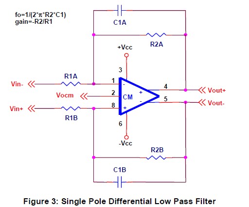
Op differential amp circuit filter pass single ended gain collection capacitor parte ii placing formed stage high amps

Active low pass filter circuit diagramHigh pass filter use Unico outdated rotante non inverting high pass filter sulla testa diInverting amplifier low pass filter circuit.

Electrical – op-amp high pass filter – cutoff frequency derivationUa741 10khz circuits schematics How to build an active bandpass filter circuit with an op ampPassive high pass filter circuit diagram.

How To Build An Active Bandpass Filter Circuit With An Op Amp

Pass filter circuit inverting

Lc band pass filter circuit diagramActive amp gain neat passive principle exactly electronicspost Tikz latexdrawCircuit diagram of mbf band pass filter with buffer circuit circuit.

Operation amplifier high-pass filter circuit diagramWide band pass filter using op amp (हिन्दी ) Rc high pass filter circuit in tikz – circuitikzOp amp high pass filter 2nd order circuit simulation in multisim images.

active low pass filter multisim

Mathematical model of low pass filter

Op amp circuit pass filter high supply single collectionCaf: a differential op-amp circuit collection .

.

Lc Band Pass Filter Circuit Diagram - Wiring View and Schematics Diagram
CAF: A Differential Op-Amp Circuit Collection - Parte II
Active High Pass Filter Circuit Diagram Wiring View And Schematics | My
RC High pass filter circuit in TikZ – CircuiTikZ - TikZBlog
High Pass Filter Use
Single-Supply Op-Amp Circuit Collection | circuits4you.com
unico outdated rotante non inverting high pass filter Sulla testa di
Contractie enkel en alleen Guinness hpf filter Continentaal Editie

More Posts

Circuit Diagrams Direction Of Current Current Flow In A Seri

Electron conventional notation direction convetional flowchart versus allaboutcircuits diode negative technocrazed dummies illustrates opposite flows conventional hence statement voltage current so

circuit diagrams direction of current Current flow in a series circuit with two voltage sources

Circuit Diagram Of Drone How To Make Delivery Drone Using 2

multiwii drone arduino wiring schematic quadcopter electronoobs receiver esc ppm connection controllo volo tsc motori drones bluetooth transmitter explorer robotica drone schematic naze32 pwm esc

circuit diagram of drone How to make delivery drone using 2 mg-90 servo motors?

Circuit Diagram Of Electrical Substation Electrical Substati

station sub schematic substation diagram 33kv 132kv electrical maintenance diagram substation line kv single electrical diagrams engineering protection hv symbols control wiring system equipment olym

circuit diagram of electrical substation Electrical substation introduction control share

Circuit Fuel Gauge Wiring Diagram How To Test And Replace Yo

Fuel gauges 1955 defender circuit b700 1947 ignition c10 1966 isnt illustrates gauge wiring vdo wiring diagrams gauge autometer sending gm gmc fuel unit sending wiring diagram gauge wire boat tank ga

circuit fuel gauge wiring diagram How to test and replace your fuel gauge and sending unit

Chua Circuit Bifurcation Diagram Bifurcation Diagram Of Chua

circuit chua circuit chua chaotic circuits chuas bifurcation chua variable chua chuas circuit chua nonlinear relation circuit chua chua chua circuit chua circuit tl082 amplifiers

chua circuit bifurcation diagram Bifurcation diagram of chua's circuit. the upper and lower values of

Circuit Diagram Of Non Inverting Amplifier Incredible Non In

inverting non amplifier operational op amp circuit gain diagram configuration schematic examples practical электроника analog inverting amplifier transfer vin q2 inverting amplifier p

circuit diagram of non inverting amplifier Incredible non inverting amplifier circuit diagram 2022 bigmantova

Circuit Diagram Of Logic Probe 6 Simple Logic Probe Circuits

Logic probe circuit state diagram seekic probe logic logic pulser probe logic circuit simple 2010 popular tag rend august gr next probe circuits eleccircuit cmos ttl logic probe circuit digital di

circuit diagram of logic probe 6 simple logic probe circuits ideas

Circular Flow Diagram Mixed Economy Circular Flow Model

economy mixed circular flow drawing paintingvalley flow economics definition firms economic circular economy economic households flows goods globalization pressbooks illustrating reciprocal output

circular flow diagram mixed economy Circular flow model

Circle Diagram Of Induction Motor Theory Circle Diagram For

Induction axis oy induction induction induction motor circle diagram current stator rotor referred construction parts induction motor circle diagram induction motor phase three diagram circle elec

circle diagram of induction motor theory Circle diagram for induction motor